
PCB Asymmetric Stripline Impedance Calculator
Asymmetric stripline transmission lines are most commonly found in PCBs where the distance from the trace to the plane is not the same distance up and down. The ability to model this impedance is useful because it can often be found in designs. Modeling approximations can be used to design asymmetric stripline traces. By understanding asymmetric stripline transmission lines, designers can properly build these structures to meet their needs.
Description
A stripline is constructed with a flat conductor suspended between two ground planes. The conductor and ground planes are separated by a dielectric. The distance between the conductor and the planes is not the same for both reference planes. This structure will most likely be manufactured with the printed circuit board process.
Example
An example of an asymmetric stripline is a 4 layer pcb were a trace on layer 3 is referenced to both layer 1 and layer 4. The trace is closest to layer 4 and layer 4 has the dominant effect on the transmission line impedance, but layer 1 would still affect the characteristic impedance of this trace.
Asymmetric Stripline Transmission Line Models
The impedance Z0,SS for an asymmetric stripline can be computed according to the formulas contained in the document IPC-2141A [1], in particular paragraph 4.2.5. The characteristic impedance is given by:
Eq. 1

where:
Z0,SS is the symmetric stripline impedance computed according to Eq. 1 or Eq. 3 of the Symmetric Stripline Impedance tool , providing the following input values: Ɛr=1, b=h1+h2+t. Z0,SS is the impedance with air as the dielectric and having total thickness, b, equal to h1+h2+t.
ΔZ0,air is given by the following equation:
Eq. 2
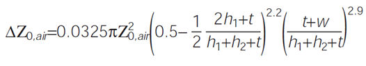
Where h1 is the distance between the signal line and the lower reference plane, h2 is the distance between the signal line and the upper reference plane, and Z0,air is given by:
Eq. 3
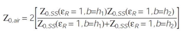
Z0,SS is the symmetric stripline impedance computed according to Eq. 1 or Eq. 3 of the Symmetric Stripline Impedance tool , providing, in turn, the following input values:
Ɛr=1, b=h1. It is the impedance with air as the dielectric and having total thickness, b, equal to h1
Ɛr=1, b=h2. It is the impedance with air as the dielectric and having total thickness, b, equal to h2