
Microstrip Line Crosstalk Calculator
Microstrip refers to the trace on the outer layer of the PCB, which is adjacent to a solid plane through a dielectric material. Crosstalk is the unwanted coupling energy between traces. There are two types: forward and backward. This tool calculates reverse crosstalk, which is usually the main crosstalk component.
Description
Microstrip refers to the trace on the outer layer of the PCB, which is adjacent to a solid plane through a dielectric material. The Microstrip method provides RF suppression on the PCB, and also allows faster clock and logic signals than sctripline. This faster clock and logic signal is due to smaller coupling capacitance and lower no-load transmission delay. The disadvantage of Microstrip is that the external signal layer of the PCB will radiate RF energy into the environment, and metal shielding is added above and below this layer.
Microstrip line: It is a strip-shaped line that runs on the surface layer (microstrip) and is attached to the surface of the PCB, as shown in the figure below.

The blue part is the conductor, the green part is the insulating dielectric of the PCB, and the small blue block above is the microstrip line.
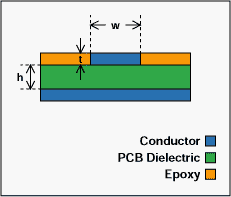
The yellow part is epoxy organic material.
Since one side of the microstrip line is exposed in the air (it can radiate to the surroundings or be interfered by the surrounding radiation), and the other side is attached to the insulating dielectric of the PCB, part of the electric field it forms is distributed in the air, and the other part is distributed in the insulating dielectric of the PCB. However, the signal transmission speed in the microstrip line is faster than that in the stripline, which is its outstanding advantage!
A microstrip line is a strip conductor (signal line) that is isolated from the ground plane by a dielectric. If the thickness, width, and distance from the ground plane of the line are controllable, its characteristic impedance can also be controlled.
Crosstalk is the unwanted coupled energy between traces. There are two types of crosstalk forward crosstalk and reverse crosstalk. This tool calculates the reverse crosstalk which is usually the dominant crosstalk component.
Backwards crosstalk creates a pulse width that is twice that of the propagation time of the pulse traveling the coupling distance. The amplitude of this crosstalk is what this tool calculates. The amplitude increases as the coupling length increases up to a point. At some point the amplitude will stay constant. The crosstalk coupling calculation requires information for the driver source as well as the PCB physical characteristics. This tool calculates the cross talk coefficient as well as the coupled voltage, both can be useful in crosstalk analysis.