
Getting Started with the S2-LP Development Kit
System Requirements
The STSW-S2LP-DK application GUI has the following minimum requirements:
1. PC running Windows operating system (7, 8, or 10) with an Intel® or AMD® processor
2. At least 1 GB of free RAM
3. USB port
4. 200 MB of available hard disk space
5. Adobe Acrobat Reader 6.0 or higher
STSW-S2LP-DK Development Kit Setup
Launch the S2-LP DK-Setup-X.X.X.exe file and follow the on-screen instructions. The SDK is installed by default in C:\\ST\S2-LP_DK x.x.x\.
· Requires IAR Embedded Workbench 8.32.1 or MDK ARM Keil V5.26.2.0.
Hardware Description
STEVAL-FKI868V2, STEVAL-FKI433V2, and STEVAL-FKI512V1 Evaluation Boards
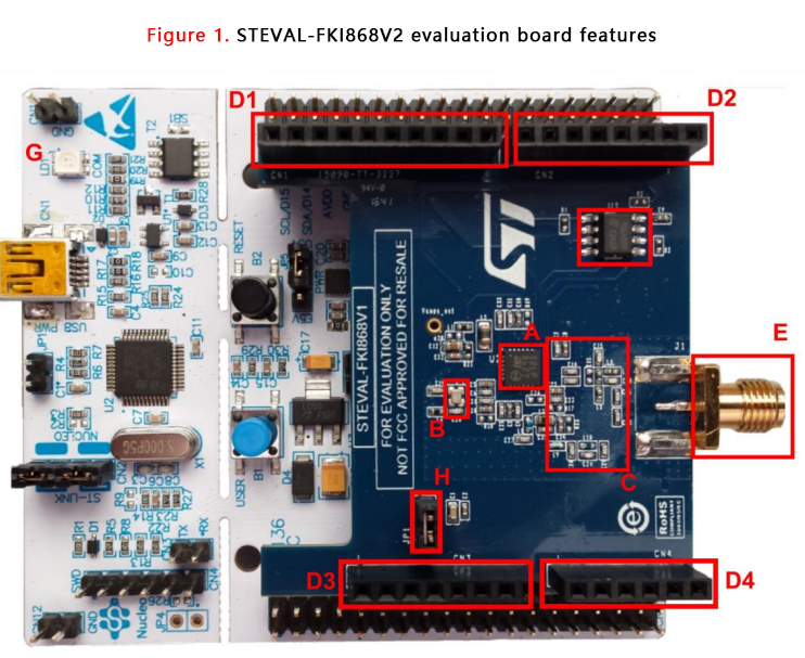
The STEVAL-FKI868V2, STEVAL-FKI433V2, and STEVAL-FKI512V1 evaluation boards are designed for operation in the 826-958 MHz, 413- 479 MHz, and 452-527 MHz frequency bands, respectively. Some of the features on the board are as follows (see Figure 1. STEVAL-FKI868V2 Evaluation Board Features):
1. S2-LP (Type A)
2. 8 MHz high frequency crystal (B)
3. Balun, matching network and harmonic filter (C)
4. Two rows of Arduino compatible connectors (D1-4)
5. SMA connector (E)
6. EEPROM for manufacturing data (F)
7. NUCLEO-L152RE or NUCLEO-L053R8 Evaluation Board (G)
8. Jumper for S2-LP current measurement (H)
STEVAL-FKI868V2, STEVAL-FKI433V2 and STEVAL-FKI512V1 Power Supply
The S2-LP board can be powered via the mini USB connector of the Nucleo Evaluation Board. When the JP1 jumper is installed (H in Figure 1. STEVAL-FKI868V2 Evaluation Board Features), the RF section is powered. By removing this jumper and connecting a power meter, you can measure the S2-LP current consumption.
STEVAL-FKI915V1 Evaluation Board
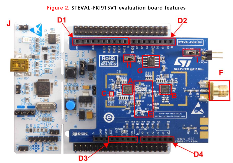
The STEVAL-FKI915V1 evaluation board is tuned to operate in the 904-1055 MHz frequency band. Features of the STEVAL-FKI915V1 Evaluation Board (see Figure 2. Features of the STEVAL-FKI915V1 Evaluation Board):
1. S2-LP (Type A)
2. Skyworks SE2435L FEM (B)
3. High-frequency 8 MHz crystal (C)
4. Two rows of Arduino-compatible connectors (D1-D4)
5. Balun, matching network, and harmonic filter (E)
6. SMA connector (F)
7. EEPROM for manufacturing data (G)
8. Jumper for S2-LP current measurement (H)
9. Jumper for Skyworks SE2435L FEM current measurement (I)
10. NUCLEO-L152RE or NUCLEO-L053R8 board (J)
GUI Software Description
The S2-LP DK GUI included in the software package is a graphical user interface that can be used to communicate with the S2-LP devices to interact and evaluate their performance. You can run this utility by clicking the S2-LP GUI icon on the desktop or under: Start → STMicroelectronics → S2-LP DK X.X.X → S2-LP DK This version of the GUI for S2-LP is specifically for RF performance evaluation and only provides RF test windows and device setting parameter operations.
Installation
To use the S2-LP GUI, make sure that the hardware and software are properly set up (S2-LP DK is installed). The firmware to be programmed is located in the S2-LP DK software package under the binary folder. To download the firmware to the internal Flash of the motherboard, follow these steps:
1. Connect the motherboard to the PC USB port
2. Open the S2-LP DK GUI
3. Select the COM port associated with the board
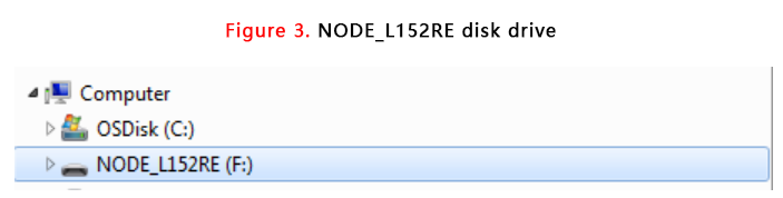
4. Open "Tools" → "Firmware Upgrade" and select the appropriate firmware by browsing, then click "Open" and wait for the firmware to download. Alternatively, the motherboard can be flashed by dragging and dropping the appropriate firmware into a disk drive recognized by Windows (such as drive F below).
The S2-LP DK GUI can only be used with one S2-LP DK - motherboard and one S2-LP RF - daughterboard connected to a PC via a USB cable. Therefore, only one instance of the S2-LP DK - GUI can be run per board connected to a PC. Figure 4. Connection Setup 1: 1 PC with S2-LP-DK GUI and Figure 5. Connection Setup 2: 2 PCs with S2-LP-DK GUI show typical connections when using one or two PCs.
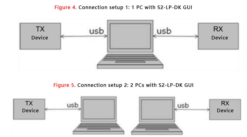
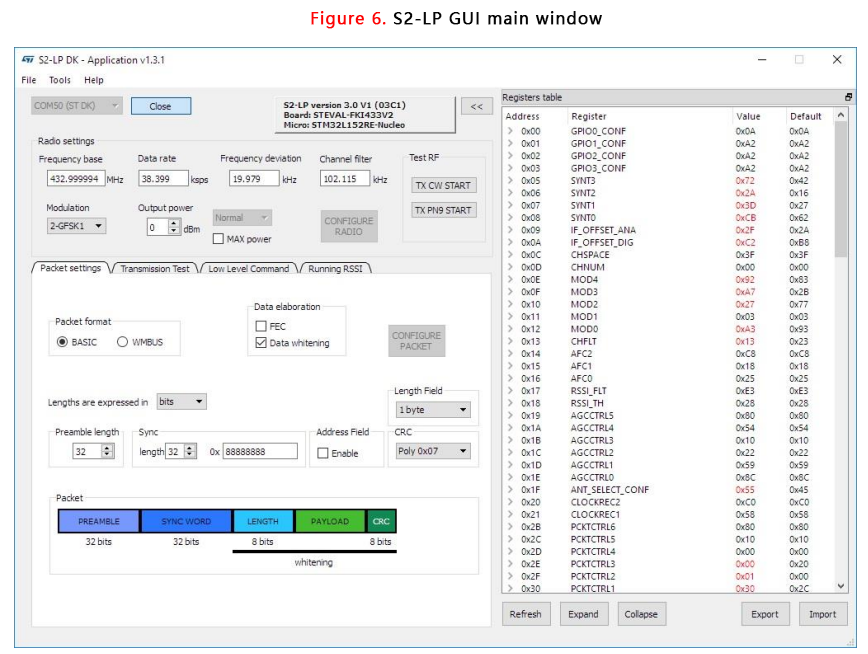
The TX device is used as a transmitter during communication testing; the RX device is used as a receiver during communication testing. The user can configure the S2-LP DK - daughterboard as either a TX device or an RX device and can change this selection dynamically before running a test. When the user runs the S2-LP DK.exe file, the S2-LP DK - GUI window appears as follows:
RF Settings Panel
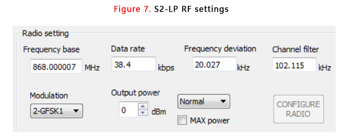
The RF Settings Panel is always displayed, informing the user of the following:
1. Frequency
2. Modulation
3. Data rate
4. Frequency deviation
5. Receive bandwidth
6. Output power
7. Frequency \u2012 Intermediate band: [413 - 479] MHz - [452 - 527] MHz \u2012 High band: [826 - 958] MHz - [904 - 1055] MHz
8. Modulation: \u2012 2-FSK \u2012 2-GFSK BT 0.5 \u2012 2-GFSK BT 1 \u2012 4-FSK \u2012 4-GFSK BT 0.5 \u2012 4-GFSK BT 1 \u2012 ASK \u2012 ALSO
9. Data rate range: [0.3 - 250] kbps.
10. Frequency deviation range: [0.793 - 761] kHz.
11. Receive bandwidth range: [1.1 – 769.3] kHz.
12. Output power range: [-30.0 14.0] dBm if normal configuration (without external PA) is selected (for STEVAL-FKI433V2, STEVAL-FKI868V2 or X-NUCLEO-S2868A2).
13. Output power range: [-5.0 28.0] dBm if PA configuration is selected (for STEVAL-FKI915V1 or X-NUCLEOS2915A1).
S2-LP Current Evaluation Tool
The S2-LP Current Evaluation Tool is a graphical user interface for analogizing the S2-LP current consumption in monitor mode. As it is only an analogy, it should not be considered a substitute for on-chip measurements which provide actual data.
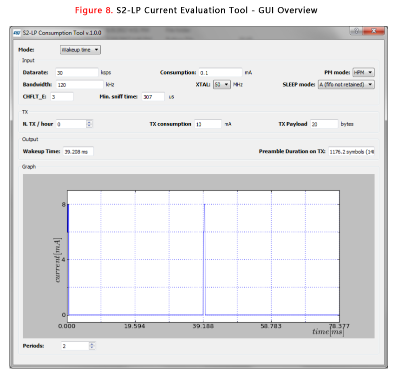
The GUI can configure two modes:
1. Wake-up
2. Current consumption
Wake-up mode
In the wake-up mode, the GUI calculates the wake-up time required to achieve the desired power consumption. The input parameters are:
1. Required communication data rate
2. Target power consumption Receive bandwidth
3. XTAL frequency
4. PM mode (HPM/LPM)
5. Sleep mode (A or B)
Power mode
In the power mode, the GUI calculates the power consumption for a given wake-up time as input data. The input parameters are:
1. Required communication data rate
2. Wake-up time Receive bandwidth
3. XTAL frequency
4. PM mode (HPM/LPM)
5. Sleep mode (A or B)